Fill-analysis
Simulation of fill levels of liquids in 3D assemblies
When designing parts and assemblies for uses cases such as pneumatics, hydraulics, lubrications, fuels or cooling cycles designers ask themselves which impact their design has on the liquids in practical use.
veoFILL provides an answer.
The easy to use stand alone software allows the analysis of CAD data from all major vendors (Catia, Creo, NX, SolidWorks, JT). You can determine adjacent hollow spaces for the mentioned use cases. veoFILL calculates volume (mm³) and generates volume 3D-models (transferable to your CAD). The volume geometrie allows you to detect connections and bottle necks within complex assemblies. In addition you can calculate based on a given volume (e.g. 3 liters) with varying gravity directions.
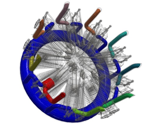
Assembly with highlighted hollow spaces
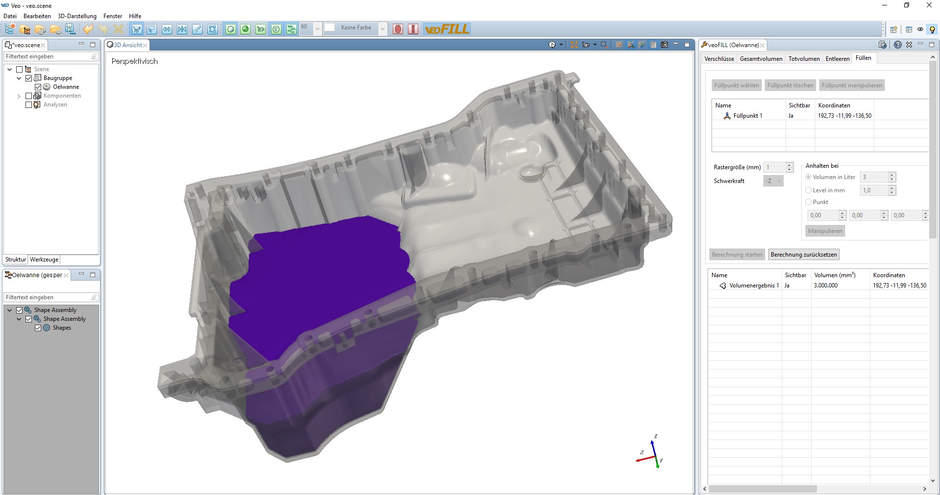
Oilpan filled with 3 liters of liquid
Features:
- Overall volume of hollow spaces within parts and assemlies
- Dead-volume with given filling/emtying point (rest liquid cant be further drained)
- Emtying with gravity direction and given emtying point
- Filling with given volume or level
-
- Comfortable fuctions for the sealing of openings in assemblies
-
- Automatic sealing
-
- Adjustable granularity (e.g. analysis of detailed hydraulic cylinder valves as well as very large off-highway engines)
-
- Import of all common CAD models (CATIA / ProE/Creo / SolidWorks / NX / JT)
Different filling modes
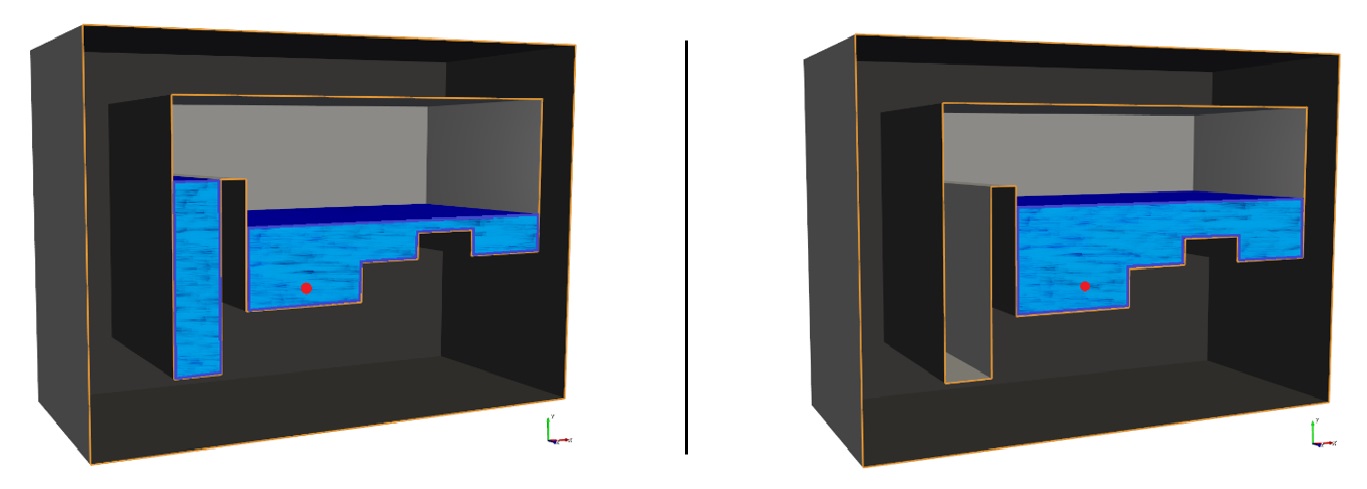
You can simulate filling and emtying processes in veoFILL. The direction of gravity can be configured. The following graphic illustrations show the different available filling modes:
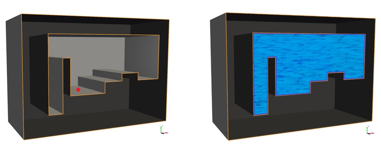
Overall volume with a given filling point
Dead-volume with given filling/emtying point (rest liquid cant be further drained)
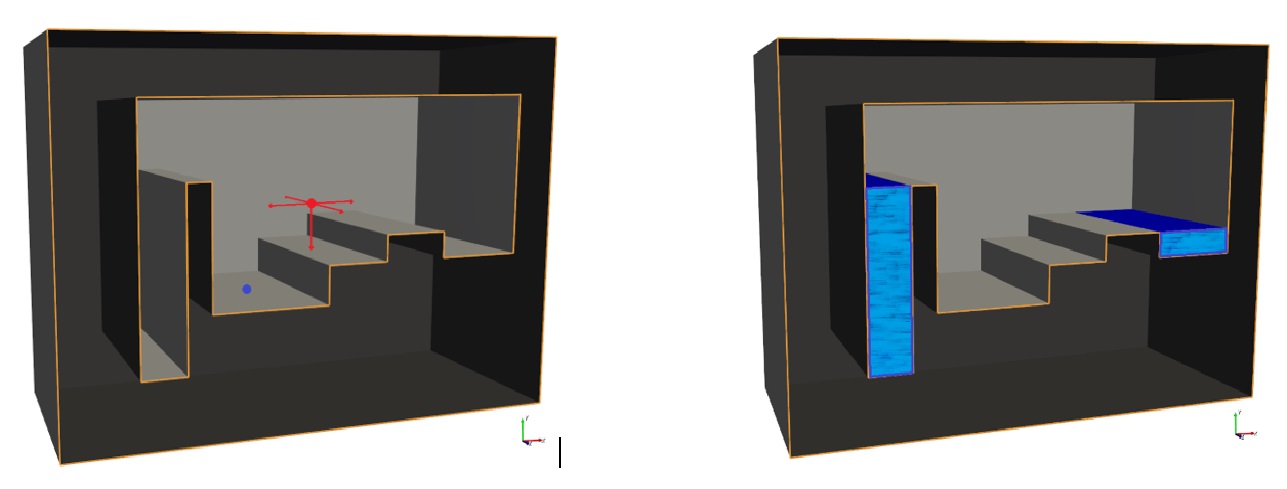
Emtying with gravity direction and given emtying point (left) and filling with given volume (right)
Closings
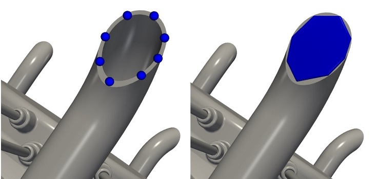
The analysed CAD assembly can be adapted before calculation. Closures help avoid unwanted openings or allow you to segregate parts simulating valve positions. The user chooses between the manual closure-types cylindrical closures, plane closure or variable closure.
Generation of a manual closure
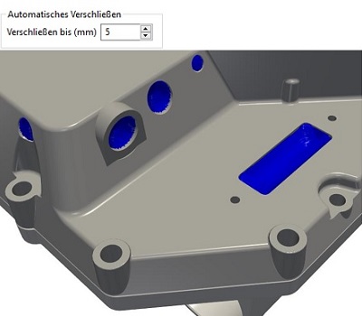
The functionality “automatic closure” avoids the drain off of liquids without any manual user interaction. The user defines the maximum size of opening that will be automatically sealed. With this functionality also very complex assemblies with a lot of external openings can be analysed with ine click. Connections within the assembly remain unaffected by the sealing.
Fill volume generated with the help of automatic closures


