Late discovery
Cost drivers such as material accumulations or missing draft angles are uncovered when there is hardly any room left for changes.

veo · Design for Manufacturing Analysis
Check castability in seconds – right on the 3D CAD model.
The problem
Simulation is specialist work and often a bottleneck. Physical trials happen after the tool is built. Following the “rule of ten”, the cost of fixing a defect multiplies by ten with every process phase it survives undetected.
Cost drivers such as material accumulations or missing draft angles are uncovered when there is hardly any room left for changes.
Every round trip to simulation, foundry or toolmaker costs weeks – in the worst case, loops run all the way back to the concept phase.
Under schedule pressure, the result is a part that is just about castable – leaving quality, weight and cost potential on the table.
The solution
The QuickCheck runs all automatic analyses – maxima, minima, gaps, isosurfaces, inner and outer edges – in one go: comprehensive results with a single click. You get first results fast and early insight into potential design problems, with the essential weak spots visible at a glance. Then rate, filter, and generate a PDF report. Done.
No gating, no cooling system, no pressure, no material definition: veo assesses the geometry directly. Material flow, cooling behavior and shrinkage-cavity risk can be estimated even without a casting simulation.
Unlike traditional CAD system analyses, which often display a large number of false positives, veo intelligently differentiates between casting-relevant thin walls and non-problematic areas: instead of sifting through hundreds of irrelevant results, you see only the really production-relevant problem areas.
CATIA, NX, Creo, SolidWorks, JT, STEP & more – a geometry description is all it takes, even with minor surface defects. Die casting, injection molding or gravity casting: you set the limits, veo checks them.
Insight
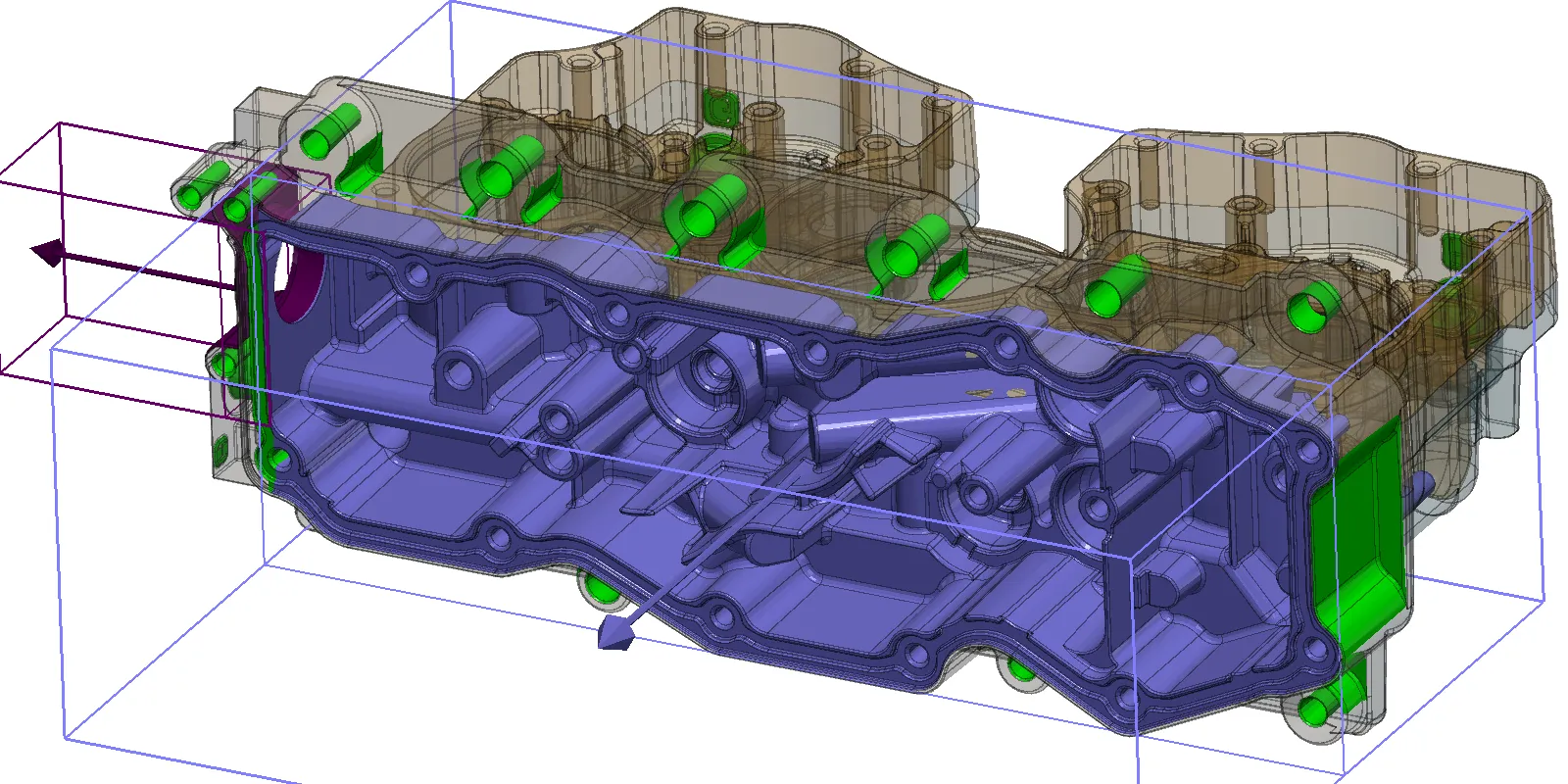
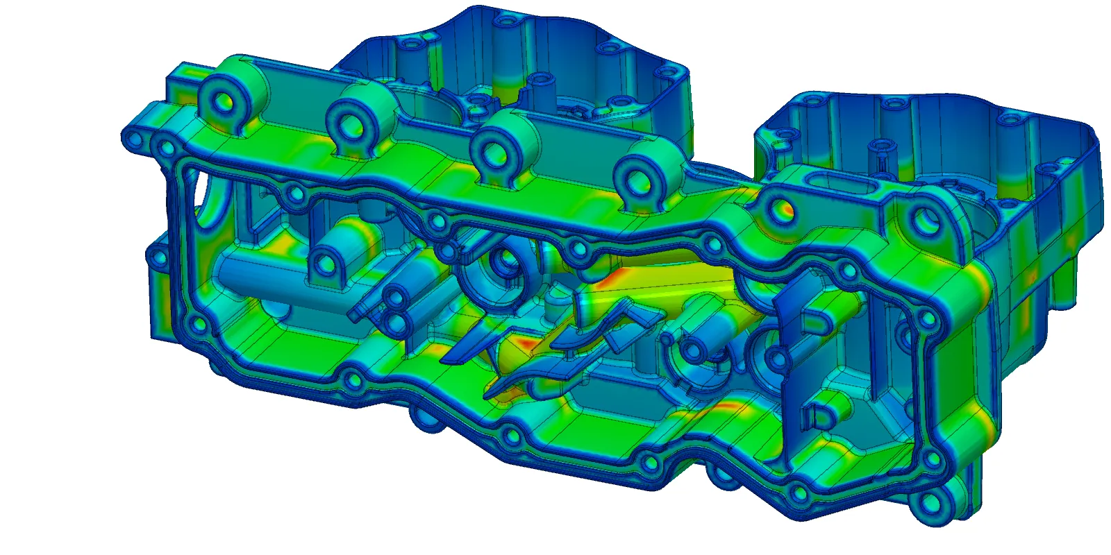
The same CAD model, two perspectives: undercuts with slide analysis on the left, wall thickness color map on the right. Drag the slider.
Capabilities
The analysis tabs in veo are meticulously crafted, each dedicated to a casting-relevant domain – from wall thickness and undercuts to draft angles. Templates tailor each analysis to your specific casting technology: define them once, share them company-wide. All results end up in a ratable result table and, on request, in a report carrying your company logo.
Full-surface wall thickness color map with histogram and saving potential in grams.
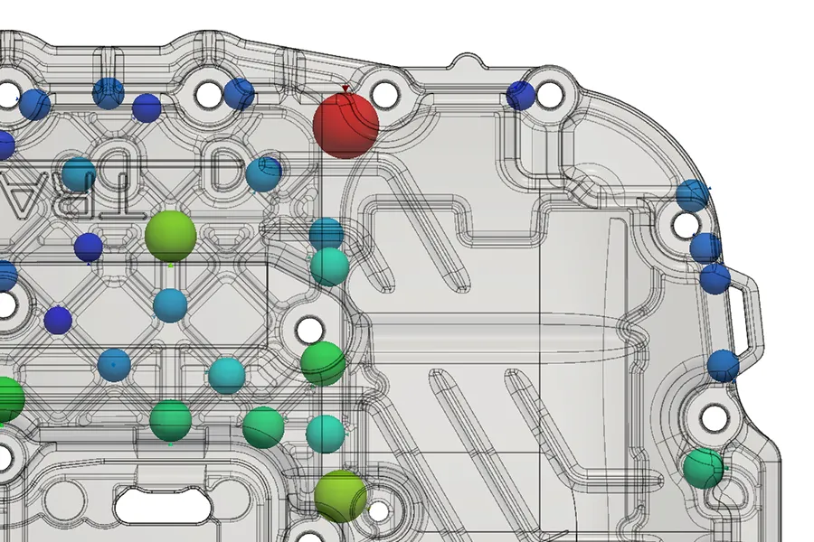
Material accumulations as inscribed spheres (Heuvers circle method) – shrinkage porosity risk located instantly.
Walls too thin to fill – found before any tool steel is cut.
Narrow gaps in the part mean fragile webs in the mold – found before the toolmaker does.
Judge cooling behavior and shrinkage-cavity risk – without any casting simulation.
Automatic parting plane proposal, projected area, clamping force and tool halves.
Draft angle color map across the whole part – for tool and slider directions.
Detected automatically, classified, and checked for demoldability.
Bundle undercuts into sliders via drag & drop – with stroke and type for tool costing.
Tool surface classification: which faces do the inserts touch, and where is draft missing?
Missing fillets checked against your curvature radius limit – preventing stress concentrations and mold wear.
PDF, DOCX, XLSX, ODT, HTML with your logo – plus a .veo file carrying the complete analysis.
The evidence
Example: pneumatic control housing of a dual-clutch transmission. In the classic flow, problem areas travel through three simulation loops and into the tool. With veo as a quality gate, the geometry is castable before the request for quotation goes out.
−66%
simulation effort. One simulation loop instead of three
−33%
moving parts. Four sliders in the tool instead of six
−149 g
less part weight thanks to early optimization
−3 months
development time. Start of production one quarter earlier
Who benefits?
Check it yourself instead of waiting: the “micro cycle” – change, check, keep designing – replaces weeks of cross-department loops. Ideally, the very first design is already manufacturable.
Better-qualified supplier selection, transparency on tool concepts and prices – and no time-consuming corrective actions, even when the supplier is contractually responsible for the fix.
Solid feasibility and cost statements within minutes in the request-for-quotation (RFQ) process: a leaner quotation workflow and a partnership of equals in the offer phase.
Trust
Teraport has been building 3D analysis software for virtual product development since 2000. veo is used on both sides of the casting process: by OEMs and suppliers in design and purchasing, and by foundries in technical sales.
What our customers say:
Since we have been using veo, the inspection process for CAD casting data has improved noticeably.
As “Competence Center Casting” we advise all development departments of the powertrain development within AUDI AG regarding the requirements of different casting technologies. The analyses of veo provide support with unique functionality and result quality. In this way, we have been able to reveal critical spots in planned castings after only a short period of use, thus avoiding high modification costs.
Especially the easy handling and fast calculation make veo an ideal tool in the virtual validation, positioned between design and casting simulation.
In our development departments we are constantly confronted with the need to ensure the feasibility of the cast process of highly complex component geometries.
Up to now, we have been hampered by a lengthy process in this area. The veo tool carries out relevant analyses within a few minutes and is designed so straightforward that it can be used directly by our designers. In addition, the quality of the results and the comprehensive filter options are convincing. Nothing but the real critical part locations is displayed.
The development time for a complex cast housing can thus be shortened by a significant amount of time.
Bocar GmbH uses veo in the development of casting molds. We are convinced by the quick calculation, detailed results and the easy handling of veo. Our users particularly benefit from the detection of thin gaps in the part that lead to thin walls in the mold. The calculation of projectile areas is also valuable to us.
Algorithms filter the results to precisely the relevant matters, so that we can find critical issues with little effort.
Try it yourself
A short message with your computer's MAC address is all it takes (ipconfig /all – physical address).
You get an immediately usable, time-limited license file and the download link for the current version.
Standard Windows installer, set up in minutes. No license server, no admin rights, no IT project – check your own parts right away.
Interfaces
veo reads native formats directly – no CAD license required.
Export results back into your world as a 3D model. Reports are available in a wide range of formats – machine-readable and AI-ready among them.